
SOFTWARE DATABASE / RELEASE RECORD
VERSION 3.3.0.11AlfaDiag Alfa Romeo and Fiat K-Line and CAN Diagnostics 3.3.0.11
Windows diagnostic software for supported Alfa Romeo and Fiat-family ECU profiles, with K-Line/CAN communication, live sensors, DTCs, actuator tests and calibration routines.
Categories
Vehicle references
Overview
AlfaDiag is a Windows diagnostic application for supported Alfa Romeo and Fiat-family electronic control units using K-Line or CAN communication. Its workspaces cover ECU identification, live sensor readings, actuator control, calibration routines, fault codes, performance recording and dyno-style analysis.
It is designed for diagnosis through a compatible interface and a matching controller profile. It should not be treated as a generic ELM-style scanner. Confirm the exact vehicle, ECU profile and protocol before connecting: similar-looking engine or ABS units may require different addresses, connector pins or message sets.
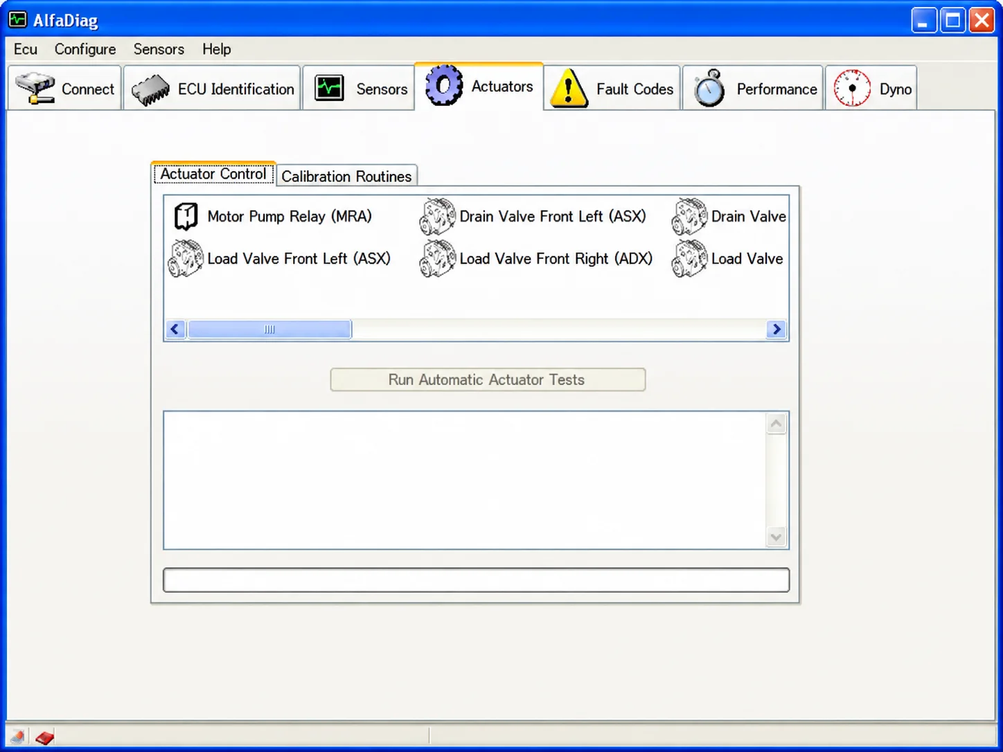
AlfaDiag Actuator Control and Calibration Routines workspace.
What This Package Is For
Identify a supported controller, document its faults, monitor live values and compare observations with known operating conditions. Use documented actuator and calibration functions only after a read-only assessment, with the vehicle secured and the required workshop conditions satisfied.
Main Functions
- Connect to a matching K-Line or CAN control-unit profile.
- Read controller identification and software information.
- Monitor multiple live sensors with current, minimum and maximum readings.
- Read supported fault codes and clear them after recording the original diagnostic evidence.
- Operate supported actuators and run automatic actuator tests.
- Access calibration routines specific to the selected controller.
- Record performance data and review it in the analysis and dyno-style workspaces.
Supported Vehicles, Systems and Control Units
- Selected Alfa Romeo and Fiat-family engine controllers covered by the installed ECU profiles.
- Engine, ABS, airbag and steering diagnosis where the appropriate system profile exists.
- The sensor interface also exposes clutch, vehicle-speed and automated-gearbox parameters.
- Available actuator functions depend on the controller profile and required operating state; a disabled control alone does not establish a vehicle fault.
- K-Line or CAN support requires a compatible adapter and the correct connector pin routing.
- Coverage is profile-specific; support is not established for every Alfa Romeo, Fiat, Lancia or Abarth model, model year, market or controller revision.
Actuator Control and Calibration Routines
The illustrated interface separates Actuator Control from Calibration Routines. Visible actuator examples include Motor Pump Relay (MRA), Drain Valve Front Left (ASX), Load Valve Front Left (ASX) and Load Valve Front Right (ADX), alongside the Run Automatic Actuator Tests control. These are examples from the displayed workspace, not a universal function list for every ECU.
Confirm the service procedure before operating a component. Secure the vehicle and keep clear of fans, pumps, valves and moving mechanisms. Calibration can alter learned values and must not be used for exploratory testing.
Package Contents
The package documentation describes a full AlfaDiag diagnostic executable selected from the supplied bundle, together with actuator/calibration and live-sensor previews. It states that the older release, loader, demo executable and accompanying source note were excluded from the prepared package, and that no vehicle logs, VINs, calibration dumps or customer records were included.
Those statements describe the documented package preparation; ECUDB has not independently inspected or executed the downloadable binary. The catalog version is 3.3.0.11. Exact software release and update dates, file size and license classification are unspecified.
PC, Interface and Workshop Requirements
- Windows workshop computer; exact supported Windows editions and architecture are not specified.
- Local administrator rights for installation and interface drivers.
- Compatible K-Line or CAN diagnostic interface, cable and correct driver for the selected controller.
- Correct adapter lead, connector pin assignment and communication route for the vehicle.
- Stable vehicle battery support appropriate to the diagnostic session.
- Reliable vehicle/controller identification and a complete pre-work diagnostic scan.
- Free storage for the extracted application, reports, logs and immutable backups.
- Current service procedure defining safe conditions for actuator tests and calibration routines.
Recommended Workflow
- Record the vehicle, model year, controller identity, software number and symptoms before starting.
- Prepare the application offline and verify that the required interface driver is installed.
- Provide stable power, select the correct controller/protocol and begin with identification or a complete diagnostic scan before any function that can change controller state.
- Save the original report, diagnostic capture or applicable memory file; retain an untouched original and use a separate working copy.
- Use only the function documented for the identified vehicle and control unit.
- Change ignition or power state only when instructed by the service procedure, then rescan and verify the repair.
- Before an actuator test, secure the vehicle and clear the working area around fans, pumps, valves and other moving mechanisms.
Important Limitations
- A brand name or menu entry does not establish support for every vehicle or controller revision.
- The application does not replace current OEM repair information, wiring diagrams or the required service authorization.
- Do not carry out configuration, key, immobilizer or programming work on an unidentified module. The diagnostic functions described here do not establish support for those operations.
- Keep original EEPROM, flash, configuration files and diagnostic captures intact; never use the sole original as a working file.
- Calibration routines may change learned values and require a documented procedure.
- Performance and dyno views are diagnostic analysis tools, not substitutes for a controlled dynamometer procedure.
Troubleshooting Checklist
- No connection: verify ignition state, battery voltage, interface driver, selected protocol and connector pin assignment.
- Controller absent from the list: confirm model year, vehicle platform, ECU family and the installed profile coverage before proceeding.
- Unreasonable readings: check units and operating conditions against an approved diagnostic platform.
- A write or configuration request is rejected: stop, retain the logs and check authorization, session conditions and power support; do not infer that an unsupported function is available.
- Application does not start: use a clean supported Windows environment and only the documented prerequisites.
- Connected but no live data: confirm the exact ECU profile, baud rate and K-Line/CAN communication route.
- Actuator buttons disabled: check that the controller supports the requested function and all prerequisite states are met.
Safety and Data Handling
Use AlfaDiag for authorized diagnostic and service work. Preserve immutable original observations and backups, and record the vehicle, controller label, interface and power conditions before making changes. Keep VINs, security credentials, customer records, active seeds, calculated responses and proprietary module files out of public support messages.
The package notes describe static inspection without launching the executable during preparation. This is not an independent ECUDB binary test or a guarantee of executable safety.
Additional Interface Preview
The Sensors workspace shows selectable channels for water temperature, estimated outside-air temperature, battery voltage, engine speed, clutch speed, vehicle speed and commanded EV current for odd gears, even gears and clutch. The displayed sensor panels include No. Flash Rewrites and Max / Min / Val fields. The status bar reads SeleSpeed CFC208F Connected; it documents the illustrated session, not universal gearbox compatibility.
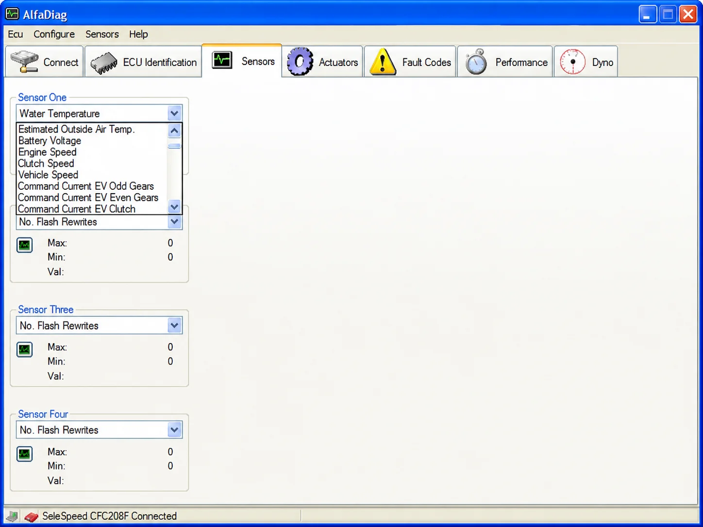
AlfaDiag live-sensor selection and monitoring workspace.
Technical Compatibility
Supported Modules
Operating Systems
System Requirements
- Windows workshop computer; exact supported Windows editions and architecture are not specified.
- Local administrator rights for installation and interface drivers.
- Compatible K-Line or CAN diagnostic interface, cable and correct driver for the selected controller.
- Correct adapter lead, connector pin assignment and communication route for the vehicle.
- Stable vehicle battery support appropriate to the diagnostic session.
- Reliable vehicle/controller identification and a complete pre-work diagnostic scan.
- Free storage for the extracted application, reports, logs and immutable backups.
- Current service procedure defining safe conditions for actuator tests and calibration routines.
Screenshots
Related Software
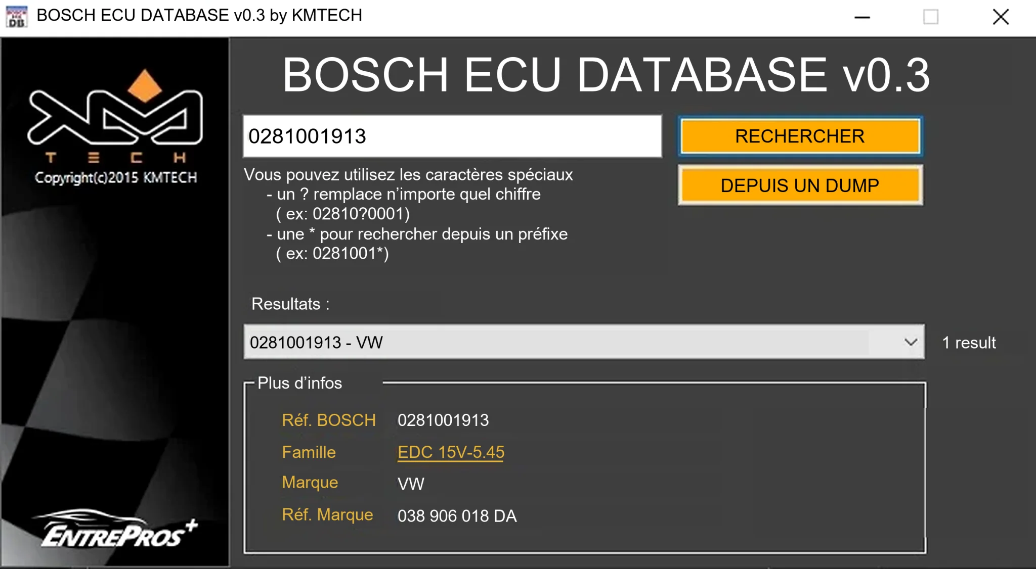
Offline Windows reference tool for Bosch ECU part numbers, controller families and OE cross-references, with exact, wildcard, prefix and binary-dump identifier searches.
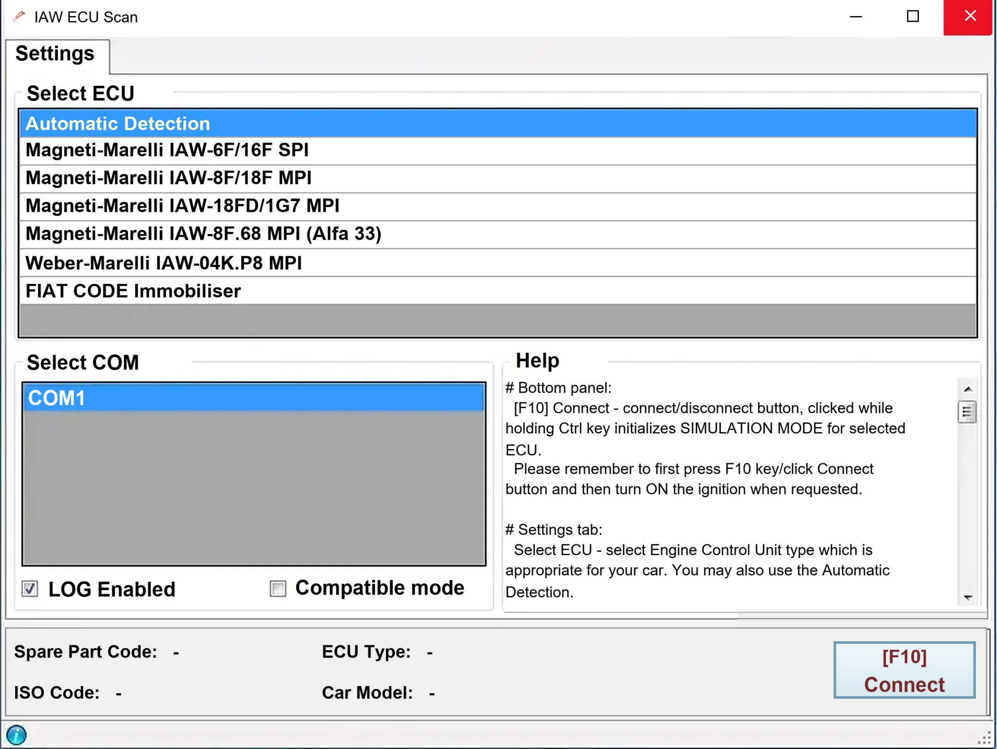
Windows diagnostics for selected legacy Magneti Marelli IAW ECUs in Fiat, Lancia and Alfa Romeo vehicles, using a KKL K-line interface for identification, faults and live data.
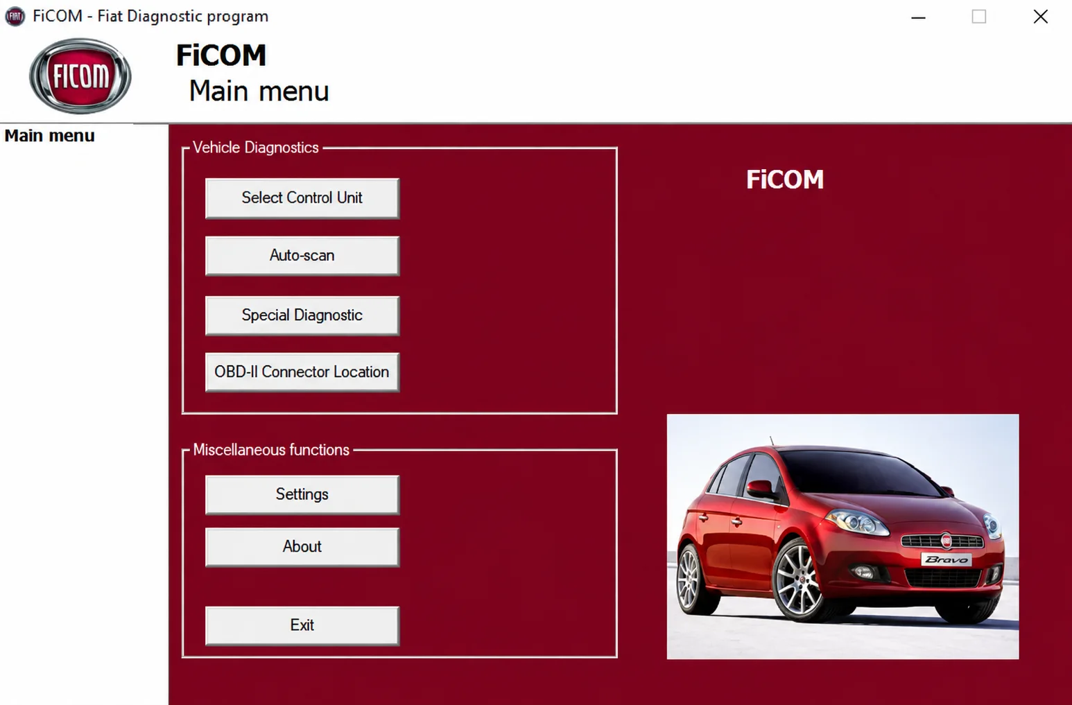
Windows diagnostics for supported Fiat-group vehicles, with ECU selection, auto-scan, fault codes, live parameters and module-specific service functions.
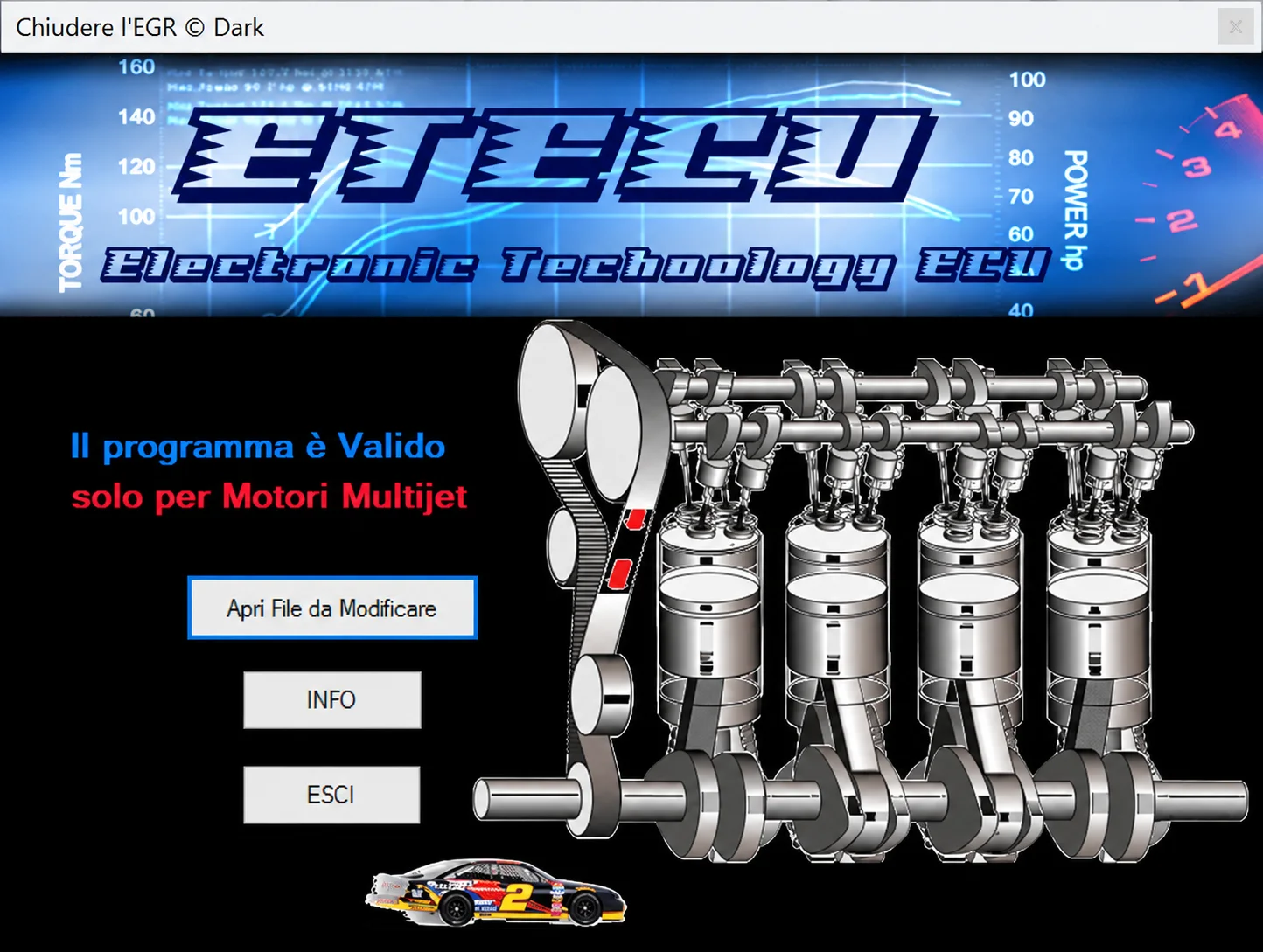
Offline Windows utility for EGR-related file processing on supported Fiat Group Multijet ECU binaries, with separate output for comparison and programming.
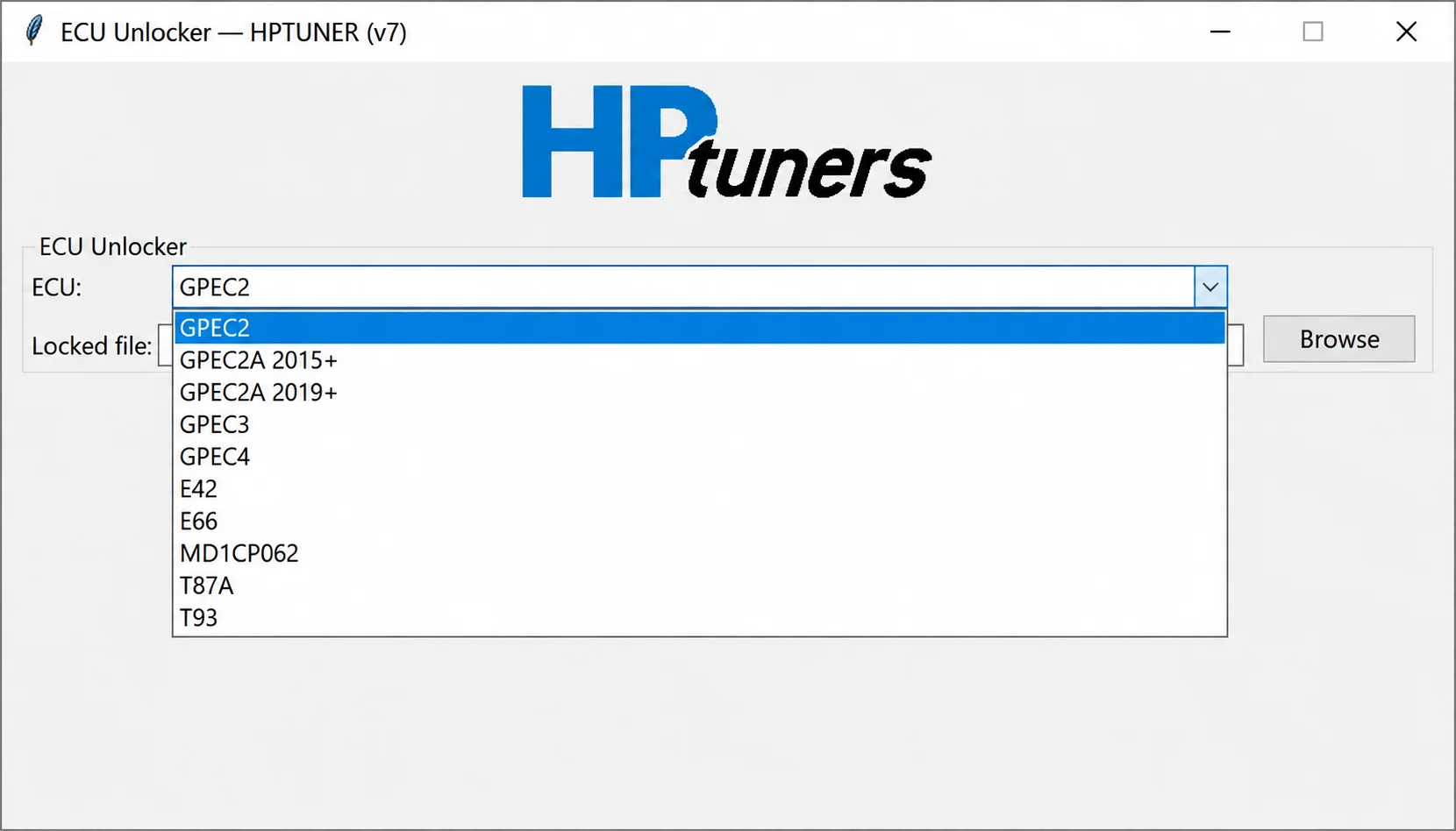
Offline controller-file processing for supported GPEC, E42, E66, MD1CP062, T87A and T93 reads, preparing working files for compatible calibration workflows.
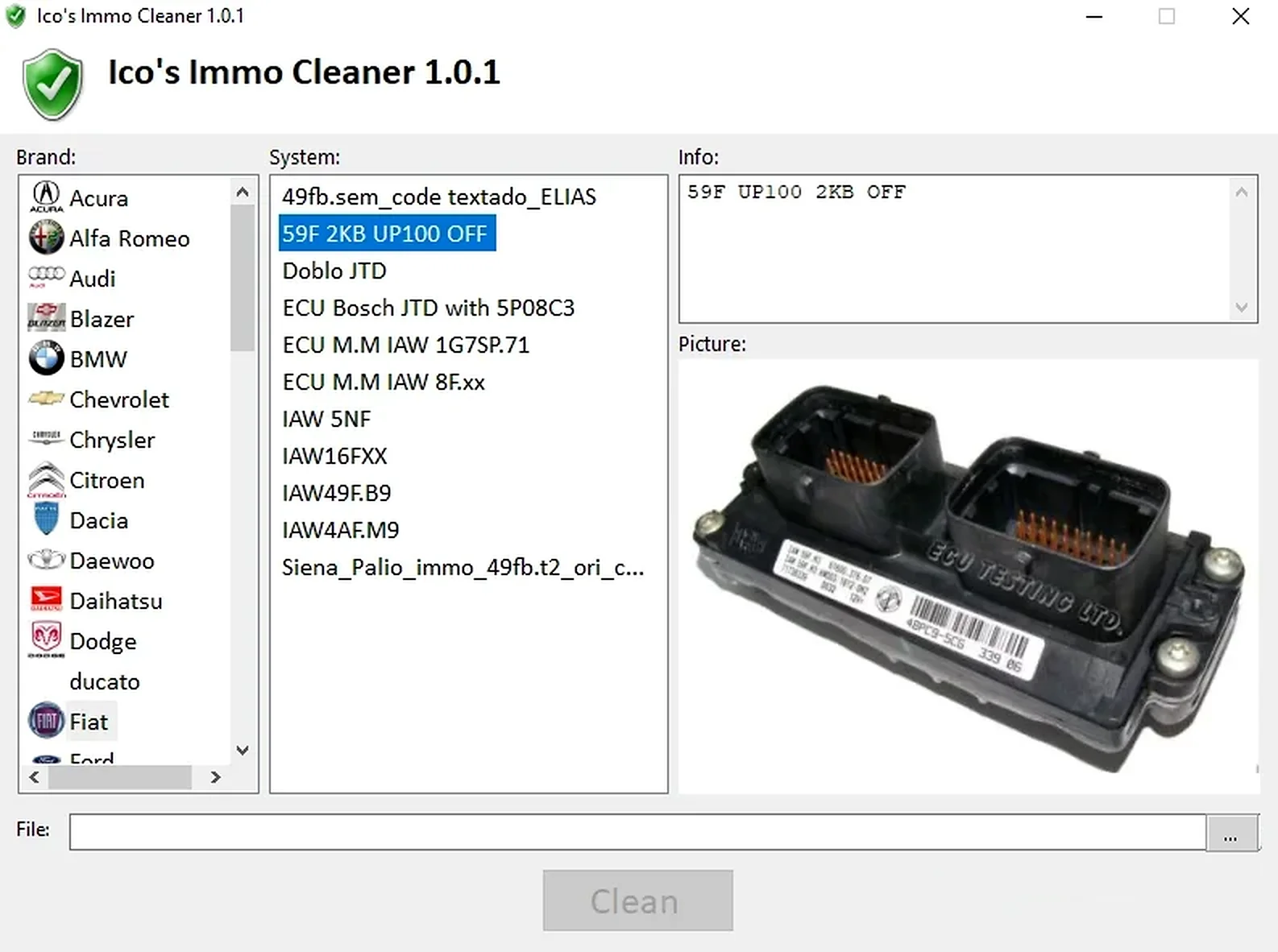
Offline Windows processor for supported ECU EEPROM and flash dumps, with brand/system selection, controller-specific clean, virgin and off templates, and reference images.